

Wins:
- Well heatsinked, well made
- Synchronous for higher efficiency
- Easily modified in useful ways
Official datasheet is here - however practical experience actually you can ignore quite a lot of it :-)
The over-current shutdown doesn't seem to work very well (I pulled 13A @ 5v out of one) and the minimum voltage spec is also pessimistic - when modded you can run them on lower voltage inputs. YMMV of course.
The main control chip is the Texas Instruments LM2727
The fets are 52N06 fets
Firstly; you MUST add electrolytic capacitors on the input and outputs or they just don't work; I put e.g. 1000uf (e.g. 35v) on the input and 2500uf on the output. You should use low-ESR caps.
Adjusting output voltage

On the PCB, VR1 is 1k, VR2 is composed of an 18k (on the left) and a 1k (right) in series = 19k.
The controller wants to see 0.6v on the FB input, so the default divider values of 1k & 19k gives you
12v 'input' (buck output) = 0.6v output (feedback to chip).
The resistor divider calc is of course (19k+1k)/1k * 0.6v =12v at Vout
When modding this board for lower voltage output I find it easiest to piggyback an extra 0402 resistor on top of the 18k one
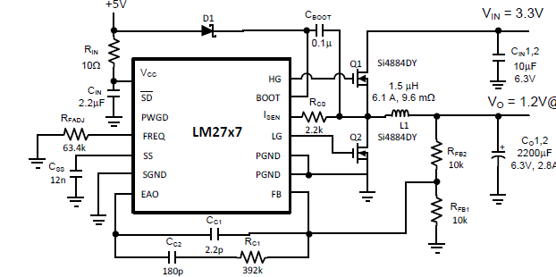
Here's the datasheet sample schematic that roughly matches what we have on the board (minus the 5v regulator, FET driver and other bits and pieces)...
Soft on/off
The transistor just above VR1 on the board is an internal on/off switch (not sure when it's used), but if you solder a wire onto the right hand side pin of it (according to the above pic) you get access to /SD; pull this low and the buck switches off. Note it has an extremely weak (microamps) 5v pullup on-chip.